Wednesday, February 26, 2014

Project 1: Optical Tremelo

This project was inspired by my obsession with this particular effect. It is a prominent effect that is used in country, blues, surf, and shoegaze music. My design was inspired by MAKE Magizine's optical tremolo box that uses a photocell, a light source, a spinning fan, and of course, quarter inch audio in/outputs.

http://makezine.com/projects/make-33/optical-tremolo-box/


Here is an example of tremolo in a popular song:


Although this design yields ideal audio results, I did not like the clunkiness of including a motorized fan. So I decided to try to make a blinking LED with a variable blink rate. To do this, I followed this schematic


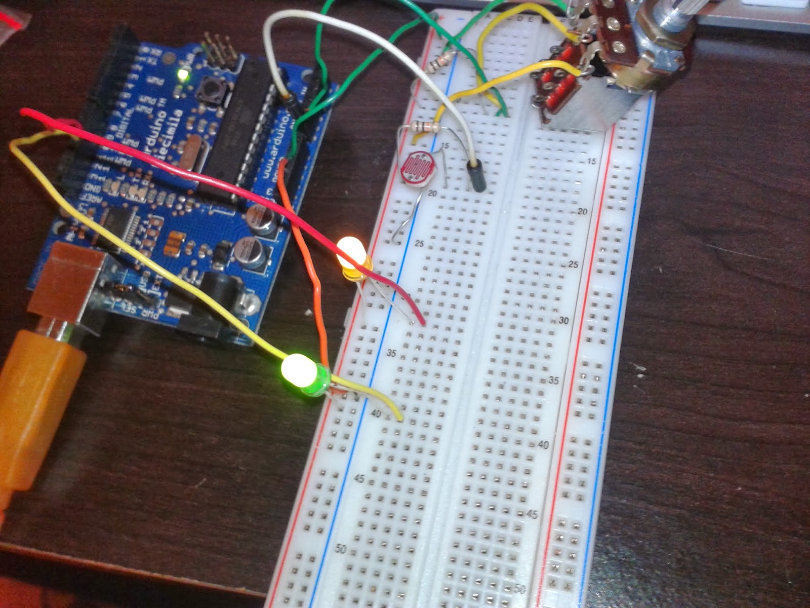
After some experimentation, I modified the circuit to use a large White LED, a small green indicator led, a 47uf Capacitor, a 100 ohm resistor next to the led, and a 10k ohm potentiometer to the capacitor. Also, I wired a switch between the emitter and positive, so that I could turn on the led, thus turning off the tremolo effect.


The second part of the circuit seemed straightforward. I simply wired two quarter inch jacks together and between the junction of the two inside pots, I soldered a photocell. I put everything inside of an unused pedal box and wired it to a 9 volt battery. I made sure to use duct tape to line the interior so that exposed medal parts did not touch the casing. Two major problems arose. The first problem was a loud clicking noise. The sound seemed to overpower my guitar and the click was in conjunction with the rate of the flashing led. The clicking speed could get so fast that it would produce a tone, just like an analog synth. Sounds cool, but not what I am trying to achieve. I theorized that excess electricity was causing the blinking. I tried adding resistors and capacitors adjacent to the photocell. I then tried a 6.8uf capacitor and it worked! But there was still a noticeable problem; no tremolo. The blinking led was too dim to complete the circuit. This could have been caused by a dying battery, a fried capacitor, too much resistance, or something else that I do not know of. After all those hours soldering my blinking led circuit, I turned to Arduino in defeat. 


What took me hours on a circuit board took me a few minutes to do in Arduino. I simply referred to part one of exercise 5 and the rate of the led pulse was relative to how much resistance the 10k ohm potentiometer put on the led. The tremolo worked like a charm and I got to enjoy playing guitar out of it.

int sensorPin = A0; // variable for analog pin (specified as A0-A5)
int sensorValue = 0; // variable to read sensor value
int ledPin = 13; // change LED blink rate based on sensor input!
void setup() {
  pinMode(ledPin, OUTPUT);
}
void loop() {
  
  // read the sensor's value (0-1023**)
  sensorValue = analogRead(sensorPin);
  
  // set the LED's blink to the sensor value
  digitalWrite(ledPin, HIGH);
  delay(sensorValue);
  digitalWrite(ledPin, LOW);
  delay(sensorValue);
}

My main frustration with the integration of Arduino is that my pedal is dependent on a laptop. Therefore I could not practically use it in a live setting. Also, I feel like the Arduino did everything for me without any discipline. Through failure and success, I learned a lot about soldering, reading schematics, and applying many of the basic electronic components I learned in class.

Monday, February 24, 2014

Excercise 5

Analog Input/Output

Part 1

This part of the exercise is straightforward. I simply copied and pasted the code into the Arduino environment and wired my breadboard according to the fritzing schematic. I do not see where I needed to modify the code or the fritzing schematics. I just followed the directions and got the results I expected; a flashing led who's pulse rate is variable based on the value of the potentiometer. This is the code I used:
int sensorPin = A0; // variable for analog pin (specified as A0-A5)
int sensorValue = 0; // variable to read sensor value
int ledPin = 13; // change LED blink rate based on sensor input!
void setup() {
  pinMode(ledPin, OUTPUT);
}
void loop() {
  
  // read the sensor's value (0-1023**)
  sensorValue = analogRead(sensorPin);
  
  // set the LED's blink to the sensor value
  digitalWrite(ledPin, HIGH);
  delay(sensorValue);
  digitalWrite(ledPin, LOW);
  delay(sensorValue);
}


Part 2

When I opened the fritzing schematic, I noticed that it required a FSR (force sensitive resistor). I do not have one included in my kit, so i decided to just leave the additional sensor out of my circuit. this is the code that I wrote for this circuit:

int potPin = 1;
int potpin2 = 0;
int ledPin = 10;
int ledpin2 = 11;
int val = 0; 

void setup() {
pinMode(ledPin, OUTPUT);
pinMode(ledpin2, OUTPUT);  
}
void loop() {
  val = analogRead(potPin);   
  digitalWrite(ledPin, HIGH);  
  delay(val);                 
  digitalWrite(ledPin, LOW);   
  delay(val);   
  val = analogRead(potpin2);
 digitalWrite(ledpin2, HIGH);  
  delay(val);                  
  digitalWrite(ledpin2, LOW);   
  delay(val);    
}

The leds would blink back and forth. However when I obstructed the photoresistor or turned the potentiometer knob, the green led would react by blinking more frequently. I was unsure how to make the other led blink more on it's own. I believed that because I was using a 10k ohm potentiometer instead of a 100k ohm as specified in the fritzing diagram resulted in the more frequent blinking of the green led. Things are feeling a bit hazy for me. Not exactly sure what the result should be. I understand that the diagram is highlighting three different types of voltage divider, but I am unclear as to what the final result should look like. 


Part 3

I opened the fade example and took what I learned from parts one and two to write my code:

int led = 10;
int led2 = 11;
int brightness = 0;    
int fadeAmount = 5; 
int val = 0;
int potpin = 0;
int potpin2 = 1;

void setup()  { 
  pinMode(potpin, INPUT);
  pinMode(potpin2, INPUT);
  
  pinMode(led, OUTPUT);
  pinMode(led2, OUTPUT);

void loop()  { 
  val = analogRead(potpin);
  val = analogRead(potpin2);
  analogWrite(led, brightness);
  analogWrite(led2, brightness);  

  brightness = brightness + fadeAmount;

  if (brightness == 500n || brightness == 100) {
    fadeAmount = -fadeAmount ; 
  }     
  delay(30);                            
}

I ran into a few problems. The main problem is that there was no variability in the fade rates of my leds. I tried adjusting the sensor values as suggested in the exercise, but I noticed little change. The leds blinked simultaneously instead of one after the other. I do not know if this has something to do with the dissonance between the analog ports and the digital ports. Because I could not figure out what was wrong with my code and/or circuit, I was unable to apply the low bipass filter to modify the fading. 


Unlike the last few exercises in which I understood completely, I am beginning to get lost. I understand the objective of each exercise, however I am having trouble reaching that objective. I think that the directions are unclear and there are no examples of what my end product should look like. I am a visual learner and I tend to get lost in abstract concepts. I think a demonstration would help me understand things a bit better so that I can move on to part 4. 


Tuesday, February 18, 2014

Reading Response 2

1. What ways can you validate the difference between Eastern and Western culture's ways of art interaction whether through observation or manipulation?

2. At what point in time will interactive art replace all traditional forms of "object oriented art?" Or will art that does not depend on a viewer always be considered the standard for fine art.

3. Can interactive art make people more aware about their relationship with the tangible physical world?

Monday, February 17, 2014

Excercise 4: Digital Input/Output

Excercise 4: Digital Input/Output

Part 1

I am beginning to appreciate Fritzing more. It is probably the clearest way for a visual learner like myself to set up these circuits.

Const int buttonpin = 2;  This initiates the buttin pin as a constant meaning it won't change
Const int ledpin =13; This initates the led pin as a constant

Void setup = this is a comand for reading the pushbutton status
pinMode (ledPin, OUTPUT); makes the led pin an output
pinMode (buttonpin, INPUT) makes the button pin an input

void loop (loops the command)
button State - digitalRead (buttonPin) = this command can detect the state of the button
if (buttonState == HIGH)
Digitalwrite (LedPin, HIGH); if button state is high, led turns on
else
Digitalwrite (ledpin, LOW); led turns off


Part 2

My circuit is set up, and I have rewritten the code so that both leds flash when I push the button:

const int buttonPin = 2;    
const int ledPin =  3;
const int led2Pin = 4;

int buttonState = 0;        
void setup() {

  pinMode(ledPin, OUTPUT); 
pinMode(led2Pin, OUTPUT);  

  pinMode(buttonPin, INPUT);     
}
void loop(){
  
  buttonState = digitalRead(buttonPin);    //I can adjust the digitalWrite HIGHS and LOWS to determine which 
leds turn on whether or not I am pushing the button
  

  if (buttonState == HIGH) {     
    digitalWrite(ledPin, HIGH);                       
  digitalWrite(led2Pin, LOW);  
  } 
  else {
    digitalWrite(ledPin, LOW);
   digitalWrite(led2Pin, HIGH); 
  }
}

My modified Digitalinout
I have now added a Pizo Speaker as an additional Output
In my code, I have included 
const int pizopin = 10
pinMode(pizopin, OUTPUT)
digitalWrite(pizopin, LOW);
digitalWrite(pizopin, HIGH);
I have now modified the code so that when I push the button, the two LEDs turn off, and the speaker buzzes. 


Part 3

I decided to use the same fritzing schematic, using the Pizo speaker. I modified the code to simulate an alarm, complete with flashing LEDs and buzzing when the button is pushed.
const int buttonPin = 2;    
const int ledPin =  3;
const int led2Pin = 4;
const int pizoPin = 10'


int buttonState = 0;        
void setup() {

pinMode(ledPin, OUTPUT); 
pinMode(led2Pin, OUTPUT);
pinMode(pizoPin, OUTPUT);  


  pinMode(buttonPin, INPUT);     
}
void loop(){
  
  buttonState = digitalRead(buttonPin);  

 if (buttonState == HIGH) {     
digitalWrite(ledPin, HIGH);
delay(250);  
digitalWrite(ledPin, LOW);
delay(250);                             
digitalWrite(led2Pin, HIGH); 
delay(250)
digitalWrite(led2Pin, LOW); 
delay(250)
digitalWrite(pizoPin, HIGH)
delay(250)
digitalWrite(pizoPin, LOW)
delay(250)    

  } 
  else {
   digitalWrite(ledPin, LOW);
   digitalWrite(led2Pin, LOW);
   digitalWrite(pizoPin, LOW); 
 
  }
}


final thoughts: While this exercise was pretty daunting, everything is coming together. I am beginning to understand the Arduino language and how it goes hand-in-hand with the fritzing environment.


Excercise 3: Hacking a Toy

(http://i.ebayimg.com/t/Cool-Catfish-Singing-Fish-Like-Big-Mouth-Billy-Bass-/00/s/MTIwMFgxNjAw/z/7OIAAMXQgb1RO6Py/$T2eC16FHJF8E9nnC6MvrBRO6PyY,Pw~~60_35.JPG)

In this exercise, I found a singing fish wall mount. This novelty toy tells very horrible fish puns and it sings as well. It's speech is initiated by a button as well as a photo resistor that can detect movement. When it sings, it activates two motors, one at the head and midsection of the fish. The head motor creates the illusion of mouth movement when the fish speaks like a puppet. The motor at the mid section makes the fish flail. The motor is connected to some gears that puts the entire body in motion. It is covered in a latex fish skin.


When I took it apart, I noticed that the main components were a speaker, a button, a photo resistor, two motors on the fish itself, and a circuit board. My goal was to distort the speech of the fish and to have control over the two motors. I began by using a piece of wire to create alternate connections within the circuit board, in hopes of finding a connection that would distort the speech. My first main issue was the volume of the fish. I was having trouble focusing, and did not want to distract my classmates when the fish began singing. I used alligator clips and added a potentiometer between the junction of the speaker and the circuit board. I used a 10k ohm potentiometer and it succeeded in lowering the volume. I could now focus and search for hotspots on the circuit board.


To my dismay, I did not find anything that sounded interesting on the circuit board and the speaker stopped working, so I began to investigate the motors. I connected each motor to a potentiometer and then to ground on the battery. I first began experimenting with the motor on the mid section. By turning the potentiometer, the motor would turn at different speeds. The same method worked with the other motor at the head. Using one potentiometer I figured out how to control both motors. The left pin controlled the head motor, the middle pin was connected to ground, and the right pin was connected to the mid motor. By turning the potentiometer in different directions, different motors would activate at variable speeds. The motors would also activate when I pushed the button or moved in front of the photo resistor.


Sunday, February 9, 2014

Artist Research

      One of my favorite and arguable one of the most known and innovative experimental artists of our time is Brian Chippendale. He is most known for his drumming in the band Lightning Bolt as well as his solo project Black Pus. His drumming style is fast and chaotic and he often incorporates distorted vocals within his music. His live performances involve him playing drums on top of noisey layers of tone and yelling. He wears a mask containing a contact microphone that goes through three line 6 delay pedals and within his drums are more contact mics that initiate tones when hit. The result is an extremely energetic and colorful balance of noise, texture, rhythm, and tone.
     I appreciate what Brian Chippendale does as an artist because it is extremely contemporary and original. His art style is a perfect balance between the extremely technical, mathematical, and the rhythmic and colorful. I have seen lightning Bolt perform which is Brian Chippendale along with Brian Gibson on guitar and I found myself lost in the wall of noise amongst an undulating crowd of sweaty teens. His art is appealing to the deep intellectual as well as the mindless raver. His art is an audible and visual experience. He creates an image and character in his music that is exotic and wild in direct contrast to his very average appearance outside of the context of a concert hall. I find pleasure in listening to his music, reading his comics, and listening to his collaborations with artists such as the flaming lips and the boredoms.

http://blackpusone.blogspot.com/

https://www.youtube.com/results?search_query=black+pus

Excercise 2: Blinking LED

Part 1
I found this to be fairly straightforward. I learned in this basic tutorial how to upload a command into the Arduino board.

int led = 13 means initiate pin 13 on the digital side of the Arduino
void setup means "the setup routine runs once when you press reset"
pinMode (led, OUTPUT) means it activates pin 13 as a digital output
Voidloop means that the code will be looped
Digital write (LED HIGH) turns the led on, high meaning high voltage
Digital write (LED LOW) turns the led off, low meaning no voltage
Delay (1000) there is a 1 second delay

Part2
As Carlos demonstrated in class, this step is very straight forward as well. To adjust the delay, you simply type how many millaseconds the led is on and off

Part 3
to innitiate two led's, I went into the first line of code and added "int led = 12" in the next line of code, I added pinMode (led2, OUTPUT); I then copied and pasted the digital write code and wrote "led2 HIGH and led2 LOW.
I uploaded the code into the arduino and plugged two led's into the breadboard. the flat sides of the leds were connected to "GND" on the digital side of the Arduino using jumper wires. The positive ends of the led's were wired to pin13 and pin 12. It Worked!!

Part 4
To add another led, I repeated the process I did in part 3. To change the order of the blinking, i went to the first line of code where int11 int12 int13 and changed the order of the numbers.

Part 5
For this step, I modeled my code from what I saw Leslie demonstrate in class. for each of the 3 void loops, I copied them three times so that each led blinks 3 times each. I adjusted the delay on led and led 3 blink at 500 milliseconds. The leds now blink SOS in morse code.


Excercise 1

Installing Arduino:
This process took a while and it has put me a bit behind schedule. The Arduino world, as welcoming as it looks, feels a little intimidating. I decided that I will perform all of my programming on a windows laptop. I am lessed versed in Windows and figuring out which driver I would need took me a little longer than it should have. But everything got squared away and I finally was able to turn on my Arduino.


Installing Fritzing:
Fritzing is a fairly straightforward program. I would be interested in knowing how to send out circuits to a manufacturer.
This is a basic led circuit as demonstrated by Carlos in class, represented in Fritzing