Part 1
This part of the exercise is straightforward. I simply copied and pasted the code into the Arduino environment and wired my breadboard according to the fritzing schematic. I do not see where I needed to modify the code or the fritzing schematics. I just followed the directions and got the results I expected; a flashing led who's pulse rate is variable based on the value of the potentiometer. This is the code I used:
int sensorPin = A0; // variable for analog pin (specified as A0-A5)int sensorValue = 0; // variable to read sensor valueint ledPin = 13; // change LED blink rate based on sensor input!void setup() {pinMode(ledPin, OUTPUT);}void loop() {// read the sensor's value (0-1023**)sensorValue = analogRead(sensorPin);// set the LED's blink to the sensor valuedigitalWrite(ledPin, HIGH);delay(sensorValue);digitalWrite(ledPin, LOW);delay(sensorValue);}


Part 2
When I opened the fritzing schematic, I noticed that it required a FSR (force sensitive resistor). I do not have one included in my kit, so i decided to just leave the additional sensor out of my circuit. this is the code that I wrote for this circuit:
int potPin = 1;
int potpin2 = 0;int ledPin = 10;
int ledpin2 = 11;
int val = 0;
pinMode(ledPin, OUTPUT);
pinMode(ledpin2, OUTPUT);
}
void loop() {
val = analogRead(potPin);
digitalWrite(ledPin, HIGH);
delay(val);
digitalWrite(ledPin, LOW);
delay(val);
val = analogRead(potpin2);
digitalWrite(ledpin2, HIGH);
delay(val);
digitalWrite(ledpin2, LOW);
delay(val);
}
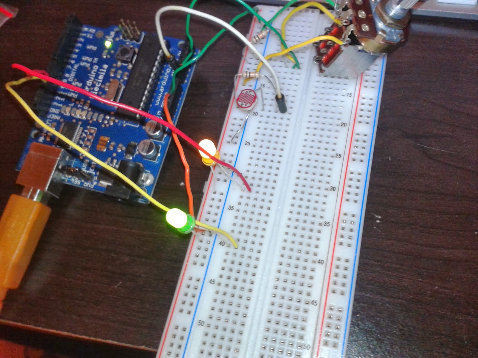
The leds would blink back and forth. However when I obstructed the photoresistor or turned the potentiometer knob, the green led would react by blinking more frequently. I was unsure how to make the other led blink more on it's own. I believed that because I was using a 10k ohm potentiometer instead of a 100k ohm as specified in the fritzing diagram resulted in the more frequent blinking of the green led. Things are feeling a bit hazy for me. Not exactly sure what the result should be. I understand that the diagram is highlighting three different types of voltage divider, but I am unclear as to what the final result should look like.
Part 3
I opened the fade example and took what I learned from parts one and two to write my code:
int led = 10;
int led2 = 11;int brightness = 0;
int fadeAmount = 5;
int val = 0;
int potpin = 0;
int potpin2 = 1;
void setup() {
pinMode(potpin, INPUT);
pinMode(potpin2, INPUT);
pinMode(led, OUTPUT);
pinMode(led2, OUTPUT);
}
void loop() {
val = analogRead(potpin);
val = analogRead(potpin2);
analogWrite(led, brightness);
analogWrite(led2, brightness);
if (brightness == 500n || brightness == 100) {
fadeAmount = -fadeAmount ;
}
delay(30);
}
I ran into a few problems. The main problem is that there was no variability in the fade rates of my leds. I tried adjusting the sensor values as suggested in the exercise, but I noticed little change. The leds blinked simultaneously instead of one after the other. I do not know if this has something to do with the dissonance between the analog ports and the digital ports. Because I could not figure out what was wrong with my code and/or circuit, I was unable to apply the low bipass filter to modify the fading.
Unlike the last few exercises in which I understood completely, I am beginning to get lost. I understand the objective of each exercise, however I am having trouble reaching that objective. I think that the directions are unclear and there are no examples of what my end product should look like. I am a visual learner and I tend to get lost in abstract concepts. I think a demonstration would help me understand things a bit better so that I can move on to part 4.
No comments:
Post a Comment